2.4 Results and analysis of the traditional mould test
Using the traditional mold structure test, it was found that the mold and the valve sealing gasket part and the cryogenic valve itself leaked. After the test, it was found that the originally tightened long bolts were loose after checking the valve and mould. According to the analysis of the test results, the long bolts become loose due to expansion caused by heat and contraction caused by cold of the material. Under a working condition of the ultra low temperature of -196℃, the linear deformation of the material is very great. The long bolts used for the clamp are straight sections and the valve body is a curved section. Because of the different lengths of the line sections, the amount of deformation is inconsistent, causing the tightened bolts to loosen. In addition, the PTFE material has features of cold flows, that is, the PTFE material undergoes plastic deformation (creep) under the action of continuous clamping load for a long time, and the gasket is severely deformed by compression. This characteristic is especially obvious under low temperature conditions, which affects the sealing effect of the gasket. After analysis, it is believed that the leakage of the cryogenic valve test is caused by the deformation under low temperature conditions. One of the reasons for the deformation is expansion caused by heat and contraction caused by cold of the valve body itself, and the other reason is the acting force on the valve body caused by the clamping force of the blind flange.
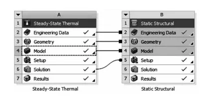
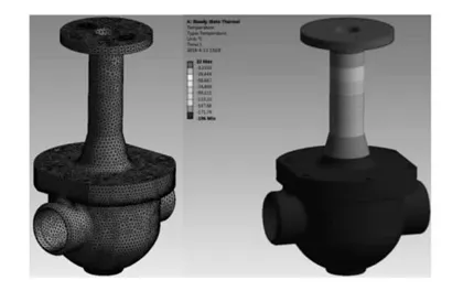
In order to verify the test conclusions and solve them reasonably, the ANSYS WORKBENCH platform was used to perform numerical simulation analysis on the valve and die model under test conditions. Taking the cryogenic ball valve as an example, the steady state thermal analysis is coupled with the structural static analysis; the low temperature load is considered; the fastening force of the blind flange is applied to both ends of the valve body, and the medium pressure is loaded at the same time. The analysis process and results of the verification test are shown in the Figure 6 and Figure 7.

Figure 6 Finite element analysis processes

Figure 7 Grid division and temperature distribution
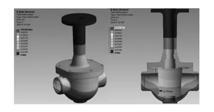
The deformation result of the valve simulation analysis verification test is shown in the Figure 8. The maximum deformation at the sealing surface is 0.75mm, and warping deformation occurs. The bolt tightening force of the traditional test mold is applied to the valve body of the ball valve, causing the sealing surface of the valve body to warp, destroying the valve sealing structure and affecting the self-sealing performance of the cryogenic valve. This must be avoided during the test.

Figure 8 Deformation results
2.5 The new type test mould
A new type of cryogenic valve test mold is introduced to overcome the shortcomings of the traditional test mold. The butt welding end of the cryogenic valve is generally designed with a deformation groove structure, which can alleviate the impact on the valve body during the valve butt welding construction. A split steel wire ring is inserted into the deformation groove, and the diameter of the steel wire ring is equivalent to the diameter of the deformation groove. Utilizing the protrusion of the wire ring relative to the deformation groove, the inlet and outlet ends of the valve clamp the combination of a pair of through hole flanges and blind flanges respectively, and use shorter double ends studs and hexagon nuts for fastening. It is sealed with a metal spiral wound gasket. The inlet and outlet blind flanges are respectively provided with connecting ends to facilitate the connection with the test system pipeline. The structure of the new valve test mould is shown in the Figure 9 to Figure 11.
1. Metal spiral wound gaskets 2. Split steel wire rings 3. Through hole flanges 4. The valve being tested 5. Double ends studs 6. Hexagon nuts 7. Blind flanges
Figure 9 The structure of the new test mould
Figure 10 The new test mould with a butterfly valve
Figure 11 The new test mould with a globe valve
The new cryogenic valve test mold adopts a structure whose two butt weld ends are combined with the clamp through hole flange and blind flange respectively, so that the stress point can be concentrated on the two butt weld ends, away from the valve sealing surface, which overcome the shortcoming of the traditional test mold causing deformation of the valve body and affecting the sealing effect. In addition, the fastening bolts become shorter, which reduces the influence of bolt deformation on the pre-tightening effect. The sealing gasket is replaced with a metal spiral wound gasket, which can not only meet the ultra low temperature working condition, but also can be used repeatedly with low costs.
3. Conclusion
The new type of cryogenic valve test mold has simple structure, convenient production, high efficiency and practicality, and is not only suitable for the test of cryogenic valves, but also can be used for various valves with butt welding ends.
Using the traditional mold structure test, it was found that the mold and the valve sealing gasket part and the cryogenic valve itself leaked. After the test, it was found that the originally tightened long bolts were loose after checking the valve and mould. According to the analysis of the test results, the long bolts become loose due to expansion caused by heat and contraction caused by cold of the material. Under a working condition of the ultra low temperature of -196℃, the linear deformation of the material is very great. The long bolts used for the clamp are straight sections and the valve body is a curved section. Because of the different lengths of the line sections, the amount of deformation is inconsistent, causing the tightened bolts to loosen. In addition, the PTFE material has features of cold flows, that is, the PTFE material undergoes plastic deformation (creep) under the action of continuous clamping load for a long time, and the gasket is severely deformed by compression. This characteristic is especially obvious under low temperature conditions, which affects the sealing effect of the gasket. After analysis, it is believed that the leakage of the cryogenic valve test is caused by the deformation under low temperature conditions. One of the reasons for the deformation is expansion caused by heat and contraction caused by cold of the valve body itself, and the other reason is the acting force on the valve body caused by the clamping force of the blind flange.
In order to verify the test conclusions and solve them reasonably, the ANSYS WORKBENCH platform was used to perform numerical simulation analysis on the valve and die model under test conditions. Taking the cryogenic ball valve as an example, the steady state thermal analysis is coupled with the structural static analysis; the low temperature load is considered; the fastening force of the blind flange is applied to both ends of the valve body, and the medium pressure is loaded at the same time. The analysis process and results of the verification test are shown in the Figure 6 and Figure 7.

Figure 6 Finite element analysis processes

Figure 7 Grid division and temperature distribution
The deformation result of the valve simulation analysis verification test is shown in the Figure 8. The maximum deformation at the sealing surface is 0.75mm, and warping deformation occurs. The bolt tightening force of the traditional test mold is applied to the valve body of the ball valve, causing the sealing surface of the valve body to warp, destroying the valve sealing structure and affecting the self-sealing performance of the cryogenic valve. This must be avoided during the test.

Figure 8 Deformation results
2.5 The new type test mould
A new type of cryogenic valve test mold is introduced to overcome the shortcomings of the traditional test mold. The butt welding end of the cryogenic valve is generally designed with a deformation groove structure, which can alleviate the impact on the valve body during the valve butt welding construction. A split steel wire ring is inserted into the deformation groove, and the diameter of the steel wire ring is equivalent to the diameter of the deformation groove. Utilizing the protrusion of the wire ring relative to the deformation groove, the inlet and outlet ends of the valve clamp the combination of a pair of through hole flanges and blind flanges respectively, and use shorter double ends studs and hexagon nuts for fastening. It is sealed with a metal spiral wound gasket. The inlet and outlet blind flanges are respectively provided with connecting ends to facilitate the connection with the test system pipeline. The structure of the new valve test mould is shown in the Figure 9 to Figure 11.
1. Metal spiral wound gaskets 2. Split steel wire rings 3. Through hole flanges 4. The valve being tested 5. Double ends studs 6. Hexagon nuts 7. Blind flanges
Figure 9 The structure of the new test mould
Figure 10 The new test mould with a butterfly valve
Figure 11 The new test mould with a globe valve
The new cryogenic valve test mold adopts a structure whose two butt weld ends are combined with the clamp through hole flange and blind flange respectively, so that the stress point can be concentrated on the two butt weld ends, away from the valve sealing surface, which overcome the shortcoming of the traditional test mold causing deformation of the valve body and affecting the sealing effect. In addition, the fastening bolts become shorter, which reduces the influence of bolt deformation on the pre-tightening effect. The sealing gasket is replaced with a metal spiral wound gasket, which can not only meet the ultra low temperature working condition, but also can be used repeatedly with low costs.
3. Conclusion
The new type of cryogenic valve test mold has simple structure, convenient production, high efficiency and practicality, and is not only suitable for the test of cryogenic valves, but also can be used for various valves with butt welding ends.
Next: Optimized Intermediate Flange Structure of Nuclear Grade Large Diameter Gate Valves (Part One)
Previous: Analysis and Improvement of Structure of the Cryogenic Valve Test Mold (Part One)

 English
 Español (España)
 العربية